Bench sheet · battery version · no mains, no wi-fi

Nest box door

A small controller that shuts the chicken nest boxes mid-afternoon and opens them again before dawn. This sheet explains every part and every wire for someone who has never built a circuit.

How to use this page

Any word with a opens a plain-English explanation. Click it. Every part on the wiring diagram opens too. Nothing on this page assumes you already know what a volt is.

Joints to solder

about 30

Bench time

one evening

Parts

$372 to $483

Tools, if you own none

about $166

Start here

Six words you need before anything else

Electricity behaves a lot like water in pipes. Every word below has a water version. Click any card for the longer story.

The one rule

Electricity only flows in a loop. It leaves the battery's + post, goes through the parts, and comes back to the post. Every wire on this page either carries it out or brings it back. The "bring it back" wires are all called .

The map

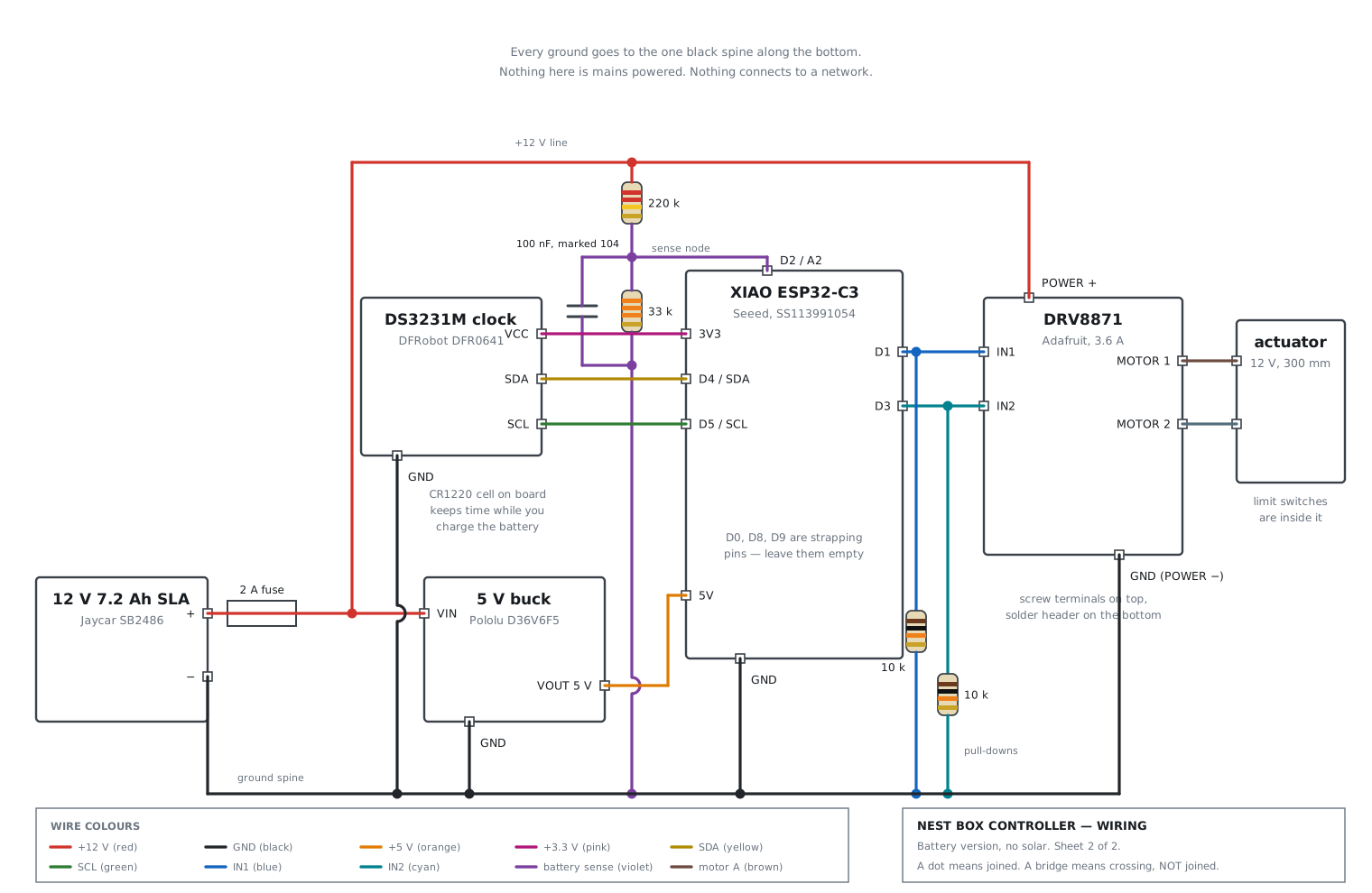
The wiring diagram

👆 Click any part: the battery, the fuse, each board, the resistors, and even the long black ground wire.

Wiring diagram

Colours

Each colour is one . All wires of one colour join together somewhere, so they all sit at the same voltage.

Dots and bridges

A filled dot means the wires join. A small arch means one wire crosses over another and does not join.

Small squares

Each white square on a board is a . The label next to it is what the board prints on itself.

Run it on screen before you build it

Wokwi is a free simulator that runs in your browser. It shows pictures of the boards, lets you drag wires between pins, and runs the real program. A ready-made project for this circuit lives in the repo. You paste two files in and press play.

A green light flashes at dawn and a red one flashes mid-afternoon. A little servo swings between them to stand in for the door. Turn the knob down past 11.9 V and watch the battery guard park the boxes open.

The simulator proves the logic. It cannot catch a swapped VIN and VOUT, a bad solder joint, or a wire on a . Building in stages catches those.

The story of one day

How the pieces work together

Read this once and the diagram stops looking like spaghetti. Power flows from left to right. Signals flow from the brain outwards.

  1. The battery pushes

    The pushes at about 12 . The sits in the red lead. If a wire ever shorts, the fuse melts and the battery cannot start a fire.

  2. The 12 V line feeds three things

    After the fuse, the red wire is called the . It feeds the buck, the motor driver's POWER terminal, and the top of the battery sense divider.

  3. The buck makes 5 V for the brain

    The takes 12 V in and gives a steady 5 V out. The XIAO board needs 5 V. Feed it 12 V and it dies instantly.

  4. The brain asks the clock what time it is

    The is a tiny computer. It talks to the over two wires, . From the date and your latitude it works out today's sunrise and sunset.

  5. The brain tells the driver to move

    When it is time, the XIAO raises one of two pins, . The sees that and connects the battery's full 12 V to the , in one direction or the other.

  6. The brain keeps an eye on the battery

    All day, the XIAO peeks at the battery voltage through the . When the battery drops below 11.9 V, the code parks the boxes open and stops moving. A flat battery therefore never locks the hens out.
Modules

The four boards

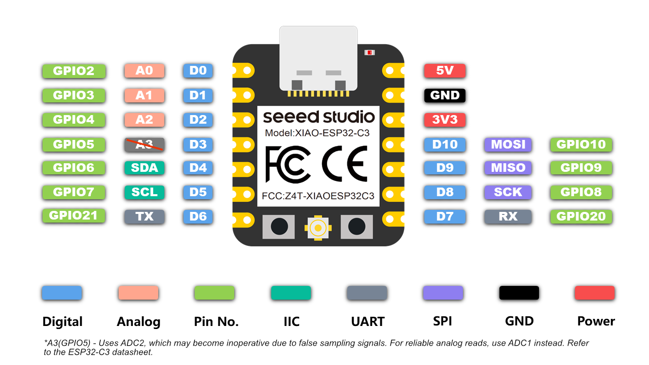
The same content as the diagram pop-ups, laid out to read straight through. Green text marks a pin you use. Red text marks a pin that must stay empty.

Official Seeed pin map for the XIAO ESP32-C3

Seeed XIAO ESP32-C3, the brain

It measures 21 × 17.8 mm. The USB-C socket sits at the top. The pin names are printed on the underside.

PinGoes to
D0GPIO2LEAVE EMPTY. It is a .
D1GPIO3driver IN1
D2GPIO4the of the battery divider
D3GPIO5driver IN2
D4GPIO6clock SDA
D5GPIO7clock SCL
D6GPIO21spare
5Vbuck VOUT
GNDthe
3V3clock VCC
D10GPIO10spare
D9GPIO9LEAVE EMPTY. It is the boot button.
D8GPIO8LEAVE EMPTY. It is a strapping pin.
D7GPIO20spare

The three red pins

The chip reads D0, D8 and D9 at the instant it powers up to decide how to boot. A resistor to ground on any of them stops the board from starting. That is why IN1 and IN2 go to D1 and D3 rather than the obvious D0 and D1.

Photo: Seeed Studio wiki

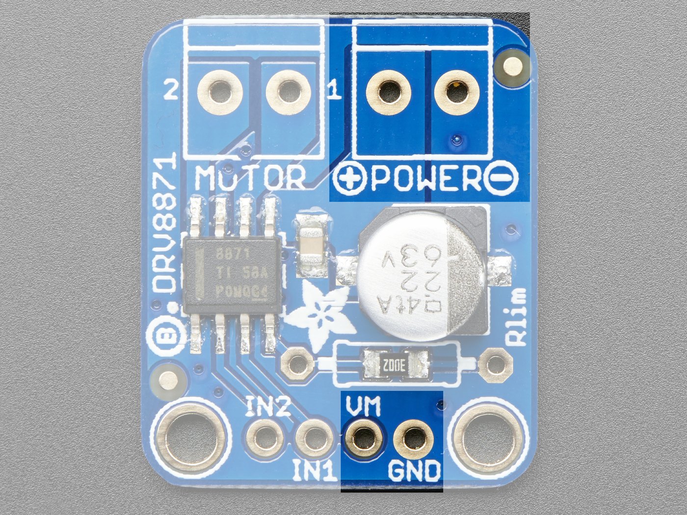
Adafruit DRV8871 showing MOTOR and POWER screw terminals and the IN2 IN1 VM GND header

Adafruit DRV8871, the motor driver

Read the in the photo. The MOTOR block has screws 2 and 1. The POWER block has + and . Four holes run along the bottom edge.

Terminal or pinGoes toSolder?
POWER +the +12 V line, from the fuseNo. It is a .
POWER −ground spineNo. Screw terminal.
MOTOR 1actuator wire ANo. Screw terminal.
MOTOR 2actuator wire BNo. Screw terminal.
IN2XIAO D3Yes
IN1XIAO D1Yes
VMSkip it. The POWER terminal already feeds it.No
GNDground spine, plus one leg of each 10 kΩ Yes

Good news

The green screw terminals arrive already soldered on. The two connections that carry the most current therefore need no soldering iron at all.

Photo: Adafruit Learning System

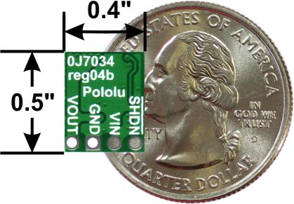
Underside of the Pololu D36V6F5 showing pads VOUT GND VIN SHDN beside a coin

Pololu D36V6F5, the 5 V buck

It measures 10 × 13 mm. The coin in the photo is a US quarter. The names are printed on the underside, which is the face shown here.

PadGoes to
VOUTXIAO 5V
GNDground spine
VINthe +12 V line, from the fuse
SHDNLeave it empty.

Read this order twice

Left to right the pads read VOUT · GND · VIN · SHDN. sit two pads apart with ground between them. Swap them and 12 V goes straight into the XIAO. Measure VOUT with the meter before you connect the XIAO.

Photo: Pololu

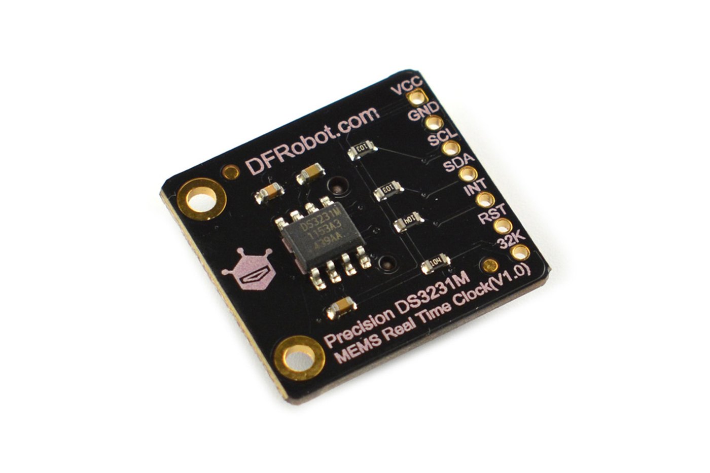
DFRobot Fermion DS3231M MEMS RTC breakout board

DFRobot DS3231M, the clock

It measures 22.5 × 21 mm. A CR1220 coin cell sits on the reverse. Seven pads run in one row.

PadPositionGoes to
VCC1stXIAO 3V3
GND2ndground spine
SCL3rdXIAO D5
SDA4thXIAO D4
INT5thnot used
RST6thnot used
32K7thnot used

SCL comes before SDA

Most clock modules print them the other way round. If you wire it from habit you will swap them, and the clock will simply not answer.

Photo: DFRobot, DFR0641

No board, no labels

The loose parts

Four resistors, one capacitor and one fuse. They come in a bag with no names printed on them, so this is where beginners get lost. Match the coloured bands to the pictures. Click any picture for the full explanation.

The confusing one

What the battery sense divider is

The XIAO wants to know how full the battery is. The only way it can "see" anything is by measuring a on one of its pins, with a part inside it called the .

There is a catch. The ADC on pin can only measure between 0 and about 2.5 V. The battery sits at 12 to 13 V. Connect the battery straight to D2 and you destroy the chip.

So we shrink the voltage first. Two in a row, one big (220 kΩ) and one small (33 kΩ), split the battery voltage between them like two people sharing a rope. The small one gets a small share: 33 ÷ (220 + 33) = 0.13, about one eighth.

The point where the two resistors meet is the . A wire runs from there to D2. A full battery at 12.6 V shows up at D2 as 12.6 × 0.13 = 1.64 V, which the ADC can read comfortably. The code multiplies the reading back up by 7.7 to get the real battery voltage.

The sits across the small resistor and smooths out flicker, so the reading holds still.

The resistors are huge on purpose. Only about 0.00005 A trickles through them, so the battery does not notice the divider at all.

How to read the coloured bands

Hold the resistor so the gold band sits on the right. The first two bands are digits. The third band says how many zeros to add. The gold band means "accurate to 5%". Your pack may have five bands instead of four. Both versions are shown when you click a resistor.

Cannot tell orange from red under your lamp? Set the multimeter to Ω, touch one probe to each leg, and read the number. That is quicker than squinting.

Two thicknesses

Which wire goes where

You need two types of wire, and the difference matters. The thin wire carries only tiny . The thick wire carries the for the motor.

RunWireColourBuy
Battery + and − to the box, through the fuse, medium duty about 1 mm²red / black1 m
The 12 V line to the driver's POWER terminalFigure-8, medium dutyred / black0.3 m
The driver's MOTOR terminal to the actuatorFigure-8, medium dutybrown / greyyour run + 1 m
5 V, 3V3, SDA, SCL, IN1, IN2, sense, light duty 26 one colour each8-colour pack
Grounds between the boardsHook-up wire, light dutyblackfrom the pack

Why the actuator run needs the thick wire

Ten metres of 1 mm² figure-8 loses about a third of a volt while the motor pulls 2 A. That loss is nothing. The same run in thin 26 AWG hook-up wire would lose over three volts and get hot. This effect is called .

Shopping, part one

Buy the parts

Everything that ends up in the finished controller. The tools you need to assemble it are in the next section. Prices were checked on 15 September 2026 and the ≈ sign means close but not verified.

Shopping, part two

Tools and consumables

These are the things you use to build it rather than things that end up inside it. Skip any you already own. There are two ways to buy: you can walk into Jaycar today, or wait a few days and pay less at Amazon. Prices and ratings were checked on 15 September 2026. The ≈ sign means close but not verified. Bold marks the better buy.

ItemJaycarAmazon AUWhy
Soldering station
adjustable temperature
TS1620
$61.95 48 W
75 W digital station
$79.98 4.6★
This purchase decides whether the evening is pleasant or miserable. A $20 pencil iron cannot hold its temperature, so the solder will not flow, so you press harder, so you tear a pad off the board. Jaycar wins on price. If you want to spend less, the 60 W 12-in-1 kit, $39.59, 4.7★ has a temperature dial and includes tips, a stand, solder and a pump.
Solder, 0.8 mm leaded NS3005
≈$25 200 g
Sn63/Pb37, 4 × 30 g
$12.99 4.8★
Leaded solder melts at a lower temperature and forgives mistakes far better than lead-free. Sn63/Pb37 beats 60/40 too. It sets instantly instead of going through a pasty stage, so a nudged joint is less likely to come out grainy.
QM1323
$61.95
AstroAI 4000-count auto-ranging
$29.99 4.6★
This one is not optional. It checks the buck before the buck touches the XIAO, it calibrates the divider, and it finds every mistake you make. The Amazon one costs half as much and picks its own range, which matters more than accuracy here.
WH5524
$29.95 160 pcs
300 pcs 3:1 glue-lined
$16.48 4.0★
Get the glue-lined 3:1 type, not plain 2:1. It melts a seal around the wire instead of just hugging it. That is the difference between a joint that survives a wet winter in a coop and one that does not.
Wire strippers and crimper
≈$30
HORUSDY 8" auto stripper/crimper
$18.50 4.3★
Strippers save more time than they cost. This one too, which covers the battery terminals.
6.35 mm female
≈$8
search for any assorted kit The battery posts are 6.35 mm blades, sometimes called F2. Any assorted crimp kit with that size will do. I have not picked one because the listings change every week.

If you own no tools at all

This table comes to about $166 at Amazon or about $217 at Jaycar. The gap is almost entirely the multimeter and the solder. Jaycar wins on the soldering station, and you can have the lot this afternoon rather than next week. If you already own a soldering iron and a multimeter, you need roughly $45 of this table.

Skill

Soldering, if you never have

Practise on the spare half of the experimenters board first. Twenty throwaway and you will have it.

  1. Set the iron to 350 °C and wet the sponge

    Do not go hotter. Hotter does not make it faster. Hotter lifts the copper pads off the board.

  2. Tin the tip

    Melt a little solder onto the tip and wipe it on the sponge. It should look bright silver. A dull grey tip transfers almost no heat, so re-tin it every few joints. This is called .

  3. Heat the metal, not the solder

    Press the tip against the pad and the pin at the same time. Count to two.

  4. Feed solder into the joint, not onto the iron

    Touch the solder to the far side of the pin, away from the tip. It should run around the pin and wrap it in half a second.

  5. Take the solder away first, then the iron

    Hold everything still for three seconds. If you move it while it sets, you get a grainy joint that fails in the coop.

  6. Look at it

    A good joint is shiny and cone-shaped, like a tiny volcano hugging the pin. A dull ball sitting on top is a . Reheat it until it collapses and flows.

The four ways this goes wrong

  1. You carry a blob over on the tip. It sticks, it looks finished, and it is not connected.
  2. You sit ten seconds on one pad. The copper lifts off and that board is scrap. If it has not flowed in three seconds, lift the iron, let it cool, and try again.
  3. You bridge two pads. This happens easily on 2.54 mm headers. Check every neighbouring pair with the meter on before you power anything.
  4. You leave no . A wire that flexes at the joint snaps in about a month, usually in the rain.

Where everything sits

The board layout

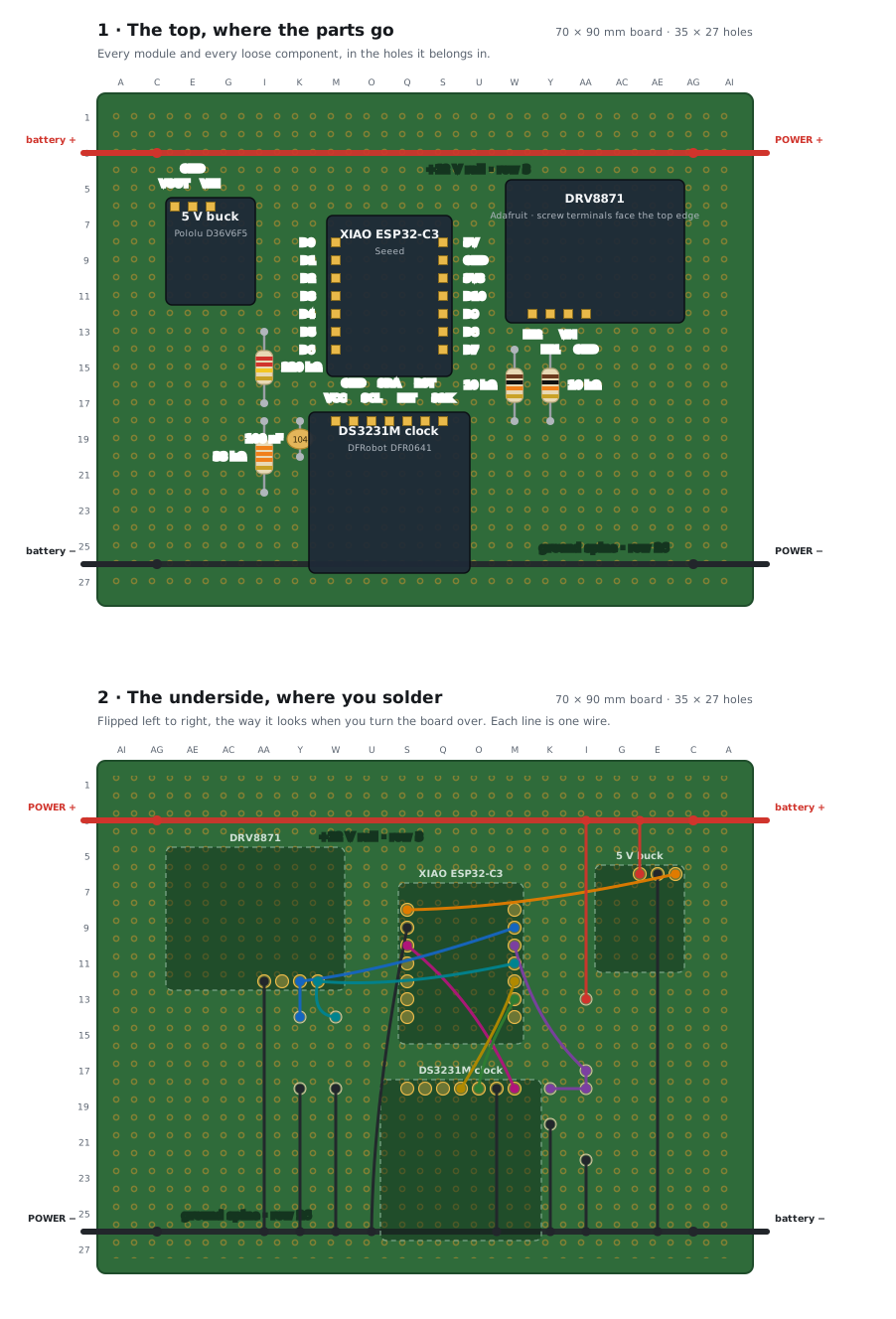
The wiring diagram tells you what connects to what. This tells you where to physically put it. The board is a 70 × 90 mm , which is 35 holes across and 27 down. It must be the plain kind, where no hole connects to any other. Stripboard, which links whole rows together, would short this layout out. Holes are named like a map: column letter, then row number. M10 is column M, row 10.

Solder the two rails first, before any module goes on

The runs along row 3 and the runs along row 26. Both are single bare wires threaded along the row and soldered at every hole they pass. Two modules sit over the top of them, so once those modules are on you cannot reach those holes again.

Perfboard layout, top view and underside view

The top panel

Where each part sits. The yellow squares are the holes its pins go through.

The bottom panel

The same board flipped over left to right, which is what you see when you turn it to solder. Every coloured line is one wire.

The colours

The same as the wiring diagram, so a violet line here is the violet line there.

Do it in this order

  1. Both rails

    Bare wire along row 3 for +12 V, and along row 26 for ground. Solder every hole the wire passes. Nothing else is on the board yet, so this is easy now and impossible later.

  2. The five loose components

    The two divider resistors, the capacitor and the two pull-downs. They lie flat against the board. Bend the legs over on the underside to hold them while you solder.

  3. Headers for the four modules

    Do not push the modules on yet. Solder the header strips alone, then check with the meter on that no pin touches its neighbour.

  4. Every wire on the underside

    Work down the list below. Tick each one off as you go. Twenty-one wires.

  5. Only now push the modules in

    Then follow build it in stages, which powers them up one at a time.

The twenty-one wires

Every one of these is a short length of thin hook-up wire soldered between two holes on the underside. The colour column is the colour to use, so the finished board reads like the diagram.

FromToColourWhat it is

Four things leave the board

The battery pair lands on the two rails at the left edge. The driver's POWER pair comes off the two rails at the right edge. Those four use the thick , not hook-up wire, because they carry the motor current. The two motor wires go straight from the driver's own screw terminals out to the actuator and never touch the perfboard.

Order of work

Build it in stages

Never wire the whole thing and then switch it on. Add one board, test it, then add the next. A fault is then always in the thing you just touched.

  1. Solder headers onto all four boards. Do nothing else yet.

    Set the meter to continuity. Check that every pin connects to its own pad and not to its neighbour.

  2. Power the buck on its own

    Connect battery → fuse → VIN and GND. Put the meter across VOUT and GND. It must read 5.0 V ± 0.1. If it reads 12 V, you have VIN and VOUT swapped, and you have just saved your XIAO.

  3. Add the XIAO

    Connect VOUT → 5V and GND → GND. Upload the program. If the light blinks, the power chain works.

  4. Add the clock

    Connect 3V3, GND, SDA and SCL. Print to the . If the time counts up, the two clock wires are right.

  5. Add the divider

    Fit the 220 kΩ, the 33 kΩ and the 100 nF. Compare what prints against the meter on the battery, then set .

  6. Add the driver and actuator, on the bench, not on the door

    Fit both pull-downs. Set to true. Run ten open-and-close cycles before it goes anywhere near the coop.

  7. Now mount it

    Use an under cover with the pointing down. Put the battery in a ventilated crate below the box, on spade terminals.

Every wire, once

Tick them off

Twenty-three connections. Tick each one as you make it. The ticks stay saved in this browser.

FromToWire
Battery +fuse → +12 V linefig-8 red
Battery −ground spinefig-8 black
+12 V linebuck VINfig-8 red
+12 V linedriver POWER +fig-8 red
Ground spinebuck GNDhook-up black
Ground spinedriver POWER −fig-8 black
Buck VOUTXIAO 5Vhook-up orange
XIAO GNDground spinehook-up black
XIAO 3V3clock VCChook-up pink
Clock GNDground spinehook-up black
XIAO D4clock SDAhook-up yellow
XIAO D5clock SCLhook-up green
XIAO D1driver IN1hook-up blue
XIAO D3driver IN2hook-up white
Driver IN110 kΩ → driver GNDresistor legs
Driver IN210 kΩ → driver GNDresistor legs
Driver GNDground spinehook-up black
+12 V line220 kΩ → sense noderesistor legs
Sense node33 kΩ → ground spineresistor legs
Sense node100 nF → ground spinecapacitor legs
Sense nodeXIAO D2hook-up violet
Driver MOTOR 1actuator wire Afig-8 brown
Driver MOTOR 2actuator wire Bfig-8 grey

Reference

Every word on this page

The same explanations that pop up when you click a word, laid out to read straight through. Grouped by topic, not alphabetically, so the basics come first.

Part

What this means